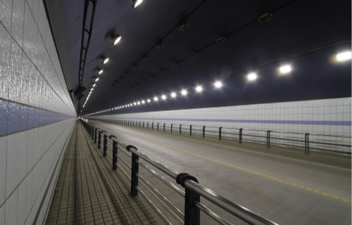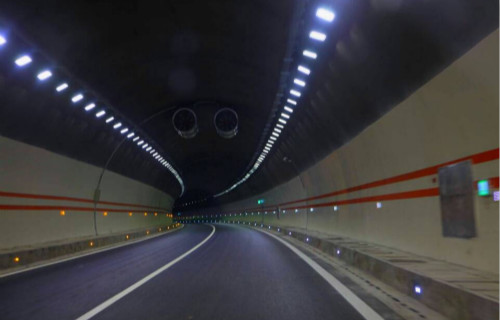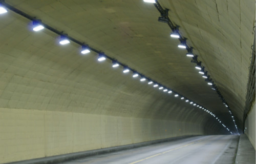


Each zone within a tunnel has its own requirements in terms of lighting design and performance. Tunnel light plays a vital role in tunnel traffic safety.
The aims of tunnel lighting are:
Firstly, to allow traffic to enter, pass through and exit the enclosed section safely
Secondly, to do so without impeding the through-flow of traffic. These aims are achieved by the adequate illumination of the tunnel interior, which allows drivers to quickly adjust to the light within, identify possible obstacles, and negotiate their passage without reducing speed. These requirements apply during the day when the contrast between outside and inside is significant and at night when it is less, but reversed.


It can be divided into five sections of illumination including lead-in section, adaptation section, transition section, basic section and exit section. The important role of each section illumination is:
1. Access zone: Eliminate the phenomenon of ‘black hole’, so that the driver can identify obstacles at the entrance;
2. Threshold zone: After entering the tunnel, the driver can quickly adapt and eliminate the "black hole" phenomenon;
3. Transition zone: The driver gradually adapts to the internal lighting of the tunnel;
4. Interior zone: basic lighting inside the tunnel;
5. Exit zone: During the day, the driver can gradually adapt to the strong light at the exit and eliminate the phenomenon of ‘bright hole’. At night, the driver can see the line shape of the external road and the obstacles on the road in the cave. Tunnel lights help eliminating the "black hole" phenomenon at the exit.
1. Calculation of road surface brightness. In order to facilitate the calculation, the average illuminance is generally calculated first, and then according to the material selected for the road surface, a conversion factor is selected, and then converted into brightness, the formula for calculating the average illuminance is:
E =NΦ SUF KK1 / (BS)
N is the arrangement mode of the lamps (2 for relative arrangement and 1 for staggered arrangement); UF is the direct light utilization coefficient of the road surface; K1 is the coefficient for increasing the illumination due to mutual reflection; Φ S is The total flux of all light sources (lm); K is the dimming coefficient; B is the road width (m); S is the lamp spacing (m). N, Φ S, B, and S are determined by design, and UF, K, and K1 are generally taken to be 0.38, 0.48, and 1.23.
2. Qualitative judgment of brightness uniformity. The uniformity of the brightness of the pavement and the lower part of the wall should meet certain requirements. After the installation distance of the luminaire is determined, the following method can be used to judge whether the uniformity is a qualified number, the relative arrangement S ≤ 2. 5h; intermediate arrangement S≤1. 5h.
3. Flicker prevention. The flicker effect is due to the discontinuous arrangement of the illuminators, and the driver's vision is constantly subjected to the stimulation of light and dark, which makes people feel uncomfortable. The frequency of the flicker effect is less than 2. 5 Hz or higher than 15 Hz. The flicker frequency (F) is mainly related to the fixture installation spacing (S) and vehicle speed (V), F = V / S.
4. Glare control. Glare is caused by a significant ratio of luminance between the task (that which is being looked at) and the glare source. Factors such as the angle between the task and the glare source and eye adaptation have significant impacts on the experience of glare. Therefore, it is necessary to avoid the use of high-brightness and large-source illumination to control glare.
SANSI offers a comprehensive range of tunnel lights paralleled by a wide variety of lighting controls adapted to tunnel applications. SANSI’s advantage with tunnel lights is patented ceramic LED technology. Ceramic dissipates heat more efficiently than aluminum and it’s not conducive to electricity allowing our LED chips to be molded directly to the ceramic.

Ceramic LEDs vs. Aluminum LEDs
Using aluminum, the LED chip(s) must be molded to a PC board with a thermal adhesive. The PC board and thermal adhesive are necessary as aluminum is a conductor of electricity. More pieces mean more heat is created as aluminum dissipates heat less efficiently than ceramic. LED chip(s) for SANSI LED Street Lights are both PC board and thermal adhesive free. The optic lens is secured to the ceramic that houses the LED chip(s).
Optics with the Light Flux Ray Method (LFR)
Using reversed optical designs and software, we simulate the optical parameters of the coverage area to calculate the lens model. Optical technology ensures that 93% of the light emitted is contained within the customized beam angle. SANSI optic lenses prevent optical loss and uniformed light distribution.
Modular Design-Wire Free, Plug-In Module Connections
There is no wire connection between the module unit and the light body making it convenient and easy for assembly and maintenance.
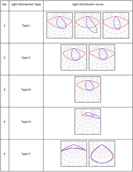
Light Distribution Customization
SANSI offers a variety of optical lenses suitable for various tunnel conditions providing uniformed light distribution.
